- 您现在的位置:买卖IC网 > Sheet目录332 > IRS210614SPBF (International Rectifier)IC DVR HIGH/LOW SIDE 14-SOIC
June 12, 2008
IRS210614S
HIGH AND LOW SIDE DRIVER
IC Features
Product Summary
? Floating channel designed for bootstrap
operation
? Fully operational to +600 V
? Tolerant to negative transient voltage, dV/dt
immune
? Gate drive supply range from 10 V to 20 V
? Undervoltage lockout for both channels
? 3.3 V, 5 V, and 15 V input logic compatible
? Matched propagation delay for both channels
? Logic and power ground +/- 5 V offset
? Lower di/dt gate driver for better noise
immunity
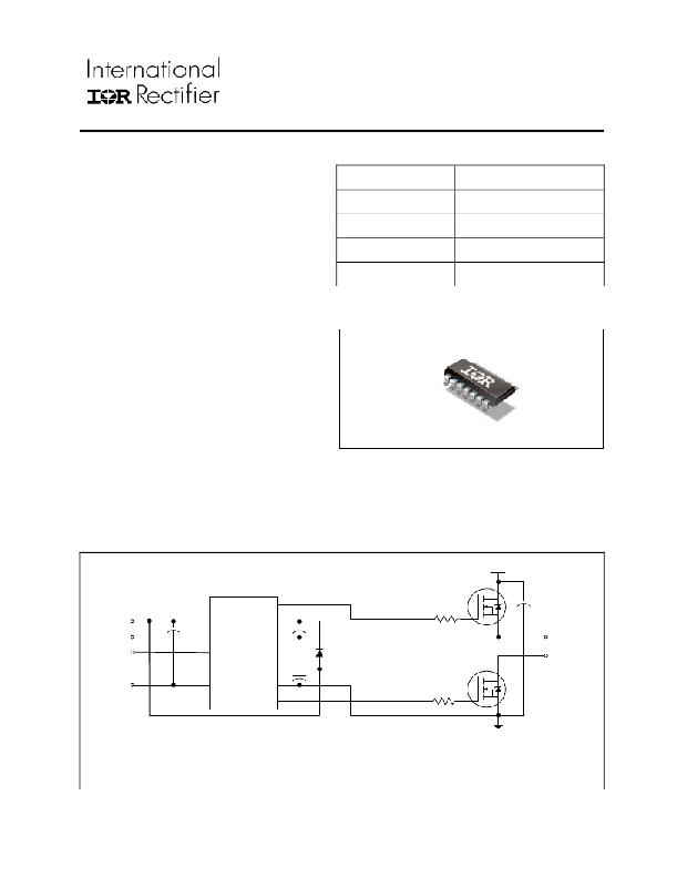
Topology
V OFFSET
V OUT
I O+ & I O- (typical)
Ton & toff (typical)
Package Types
Half-Bridge
600 V
10 V-20 V
290 mA & 600 mA
165 ns & 165 ns
? Outputs in phase with inputs
? RoHS compliant
SO14N
Typical Connection Diagram
up to 600 V
HO
V CC
V CC
V B
HI N
HIN
V S
TO
LIN
V SS
LIN
V SS
COM
LOAD
LO
Note: Please refer to page 10 for the correct pin configuration. This diagram shows electrical connections only.
Please refer to our Application Notes and Design Tips for proper circuit board layout.
www.irf.com
1
? 2008 International Rectifier
发布紧急采购,3分钟左右您将得到回复。
相关PDF资料
IRS2106SPBF
IC DRIVER HIGH/LOW SIDE 8-SOIC
IRS2108STRPBF
IC DRIVER HALF-BRIDGE 8-SOIC
IRS21091STRPBF
IC DRIVER HALF BRIDGE 8-SOIC
IRS2109SPBF
IC HALF BRIDGE DRIVER 8-SOIC
IRS2111PBF
IC DRIVER HALF-BRIDGE 8-DIP
IRS2112SPBF
IC DRIVER HI/LOW SIDE 16-SOIC
IRS2113MPBF
IC DRIVER HIGH/LOW SIDE 16MLPQ
IRS2113SPBF
IC DRIVER HIGH/LOW SIDE 16-SOIC
相关代理商/技术参数
IRS210614STRPBF
功能描述:功率驱动器IC Hi&Lw Sd Drvr All HiVolt Pins 1 Sd RoHS:否 制造商:Micrel 产品:MOSFET Gate Drivers 类型:Low Cost High or Low Side MOSFET Driver 上升时间: 下降时间: 电源电压-最大:30 V 电源电压-最小:2.75 V 电源电流: 最大功率耗散: 最大工作温度:+ 85 C 安装风格:SMD/SMT 封装 / 箱体:SOIC-8 封装:Tube
IRS21064PBF
功能描述:功率驱动器IC Hi&Lw Sd Drvr All HiVolt Pins 1 Sd RoHS:否 制造商:Micrel 产品:MOSFET Gate Drivers 类型:Low Cost High or Low Side MOSFET Driver 上升时间: 下降时间: 电源电压-最大:30 V 电源电压-最小:2.75 V 电源电流: 最大功率耗散: 最大工作温度:+ 85 C 安装风格:SMD/SMT 封装 / 箱体:SOIC-8 封装:Tube
IRS21064SPBF
功能描述:功率驱动器IC HI LO SIDE DRVR 600V 10 to 20V RoHS:否 制造商:Micrel 产品:MOSFET Gate Drivers 类型:Low Cost High or Low Side MOSFET Driver 上升时间: 下降时间: 电源电压-最大:30 V 电源电压-最小:2.75 V 电源电流: 最大功率耗散: 最大工作温度:+ 85 C 安装风格:SMD/SMT 封装 / 箱体:SOIC-8 封装:Tube
IRS21064SPBF
制造商:International Rectifier 功能描述:IC DRIVER HIGH/LOW SIDE SOIC14
IRS21064STRPBF
功能描述:功率驱动器IC Hi&Lw Sd Drvr All HiVolt Pins 1 Sd RoHS:否 制造商:Micrel 产品:MOSFET Gate Drivers 类型:Low Cost High or Low Side MOSFET Driver 上升时间: 下降时间: 电源电压-最大:30 V 电源电压-最小:2.75 V 电源电流: 最大功率耗散: 最大工作温度:+ 85 C 安装风格:SMD/SMT 封装 / 箱体:SOIC-8 封装:Tube
IRS2106PBF
功能描述:功率驱动器IC Hi&Lw Sd Drvr All HiVolt Pins 1 Sd RoHS:否 制造商:Micrel 产品:MOSFET Gate Drivers 类型:Low Cost High or Low Side MOSFET Driver 上升时间: 下降时间: 电源电压-最大:30 V 电源电压-最小:2.75 V 电源电流: 最大功率耗散: 最大工作温度:+ 85 C 安装风格:SMD/SMT 封装 / 箱体:SOIC-8 封装:Tube
IRS2106SPBF
功能描述:功率驱动器IC HI LO SIDE DRVR 600V 10V to 20V RoHS:否 制造商:Micrel 产品:MOSFET Gate Drivers 类型:Low Cost High or Low Side MOSFET Driver 上升时间: 下降时间: 电源电压-最大:30 V 电源电压-最小:2.75 V 电源电流: 最大功率耗散: 最大工作温度:+ 85 C 安装风格:SMD/SMT 封装 / 箱体:SOIC-8 封装:Tube
IRS2106STRPBF
功能描述:功率驱动器IC Hi&Lw Sd Drvr All HiVolt Pins 1 Sd RoHS:否 制造商:Micrel 产品:MOSFET Gate Drivers 类型:Low Cost High or Low Side MOSFET Driver 上升时间: 下降时间: 电源电压-最大:30 V 电源电压-最小:2.75 V 电源电流: 最大功率耗散: 最大工作温度:+ 85 C 安装风格:SMD/SMT 封装 / 箱体:SOIC-8 封装:Tube
